Lab 6: Orientation Control
3 minutes read •
Bluetooth Communication and PID/DMP Code
PID code is handeled and sent over bluetooth in a very similar fasion to lab 5!
Main Function
Here is the turning PID part of the main function. The PID turning code waits until the start_time_pid_turn flag is set to 1 via the PID_TURN_CONTROL command that is responsible for sending the Kp, Ki, and Kd gains as well as sending the starting flag: ble.send_command(CMD.PID_TURN_CONTROL, "1.5|0|40|90") # P|I|D. The getDMP and runPIDROT() functions are covered in detail in the next sections. After the turning PID arrays are filled, the robot is then instructed to stop and the sendPIDTURNData() function is used to loop through all arrays and send them over to be piped into a CVS via my notification hander.
Main Loop
if
Notification Handler
def :
try:
entry = data..
# Split by "," then extract values using fast unpacking
T, X, S, P, I, D, F = entry.
T = float
X = float
S = float
P = float
I = float
D = float
F = float
# Check if file is empty, then write headers
with as f:
f.
if f. == "":
f.
f.
except Exception as e:
```
getDMP() Function
The getDMP function is responsible for updating the global yaw_gy varaible whenever there is a new value, and if there is not (pretty rare) the previous value is used to avoid storing zeros in the yaw array. Also, it is worth noting that if we were deriving the yaw angle by taking the integral of the gyroscope’s angular velocity over time it would not make sense to then take the derivative. However, since the DMP is providing discrete angle readings, we do need to take these derivatives still.
void
runPIDRot() Function
The runPIDRot() function is responsible for calling the PID turning function (pid_turn_Gyro()) and ensuring that it has the current distance fed in as a parameter. The function also populates the PID arrays
void
pid_turn_Gyro() Function
There are three key aspects of the PID turning control loop:
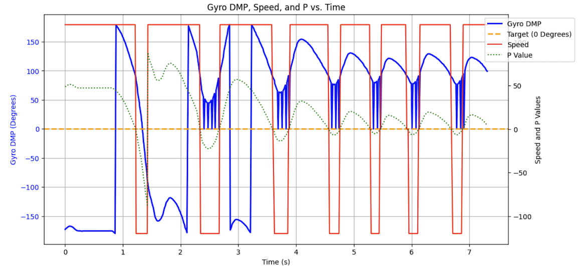
- When I first was testing with proportional and PD control, I noticed that what was really happening was that the speed was just jumping between the floor value on the negative and positve side as seen in the below image. To account for this I decided that I needed to map the calculated speeds (in the range of 0-255) into the range scaled to my robot’s floor and ceiling. This was done using the Arduino map command
speedTurn_set_mapped = map(speedTurn_set, 0, 255, minSpeedTurn, maxSpeedTurn). The result is that my robot is now using real PID control (which will be shown later) rather than just going between the PWM floor.
A low pass filter was used on the derivative term to reduce noise and the effect of derivative kick. The alpha value was calculated through a slight trial and error method where I found a balance between reducing noise (from the filtered_d_term) but also reducing speed/amplitude as fast as possible when needing to slow down (from the current d_term). The alpha that optimized this trade off was 0.1.
While testing for hours I noticed that regardless of my gains (I tried Kd terms on the order of 1000), my robot would not be able to stop in time and over shot its target. I realized that it was not a coding issue but rather the cars inability to change directions fast enough. I also noticed that the overshoot only happened on the first approach– if I picked the car up and replaced it at the beginning location after it had been running for a while the car was able to stop perfectly. To account for this, I have the car delay for 1 second at a low PWM before starting. This solved the issue completely!
int
PID Control and Gains Discussion
PID Gains
After much testing, I decided that the best final gains were Kp=1.65 and Kd=130. The Kp term is high enough to adjust and continue moving even when at small angles from the target. At the same time, it is not so big that it overshoots a large angle from the target. The Kd term is responsible for slowing down the car as it approaches the target angle. It is large enough to help slow the car down and reduce overshoot. With hours of tuning, I realized that if I continued to increase the Kd term, there would be more instability as I osccilate quickly about the target distance. The progression of choosing and testing gains is shown later. I found that my robot was able to arrive within a degree or two of the target distance and thus without the presence of considerable external noise, I did not see the need to implement integral control as well.
Testing
Disturbance Correction (PD)
Here are my two final disturbance tests. The first is with Kp=1.8 and Kd=50. You can see that the car slightly overshoots but is able to come within a few degrees of the 90 degree target each time it restabalizes.
Here is the other final disturbance test with Kp=1.65 and Kd=130. You can see that for these gains, the robot overshoots less but is just a little worst at re-aligning exactly at 90 degrees. Thus while it overshoots less, it is slower when moving to a set angle (with the increaed Kd gain that helps it slow down earlier).
Here is the plotted data after being sent over bluetooth:
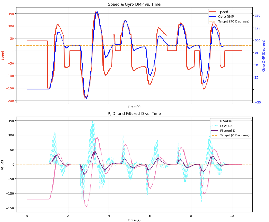
You can certainly see some derivative kick with the increased Kd term, however, the LPF does take care of it for the most part.
Turning Way Points
To start thinking about future applications of the PID controller I added waypoints that the robot would turn to. During navigation this can be implemented along side of the straightline PID controller; the robot doesn’t need to turn in an arc while it drives, instead it can drive straight, pivot, then drive straight again. In this example, the robot turns from 0 degrees to 90 degrees, then back to 0 degrees, then ends at 120 degrees:
Here is the graph for my waypoint setting:
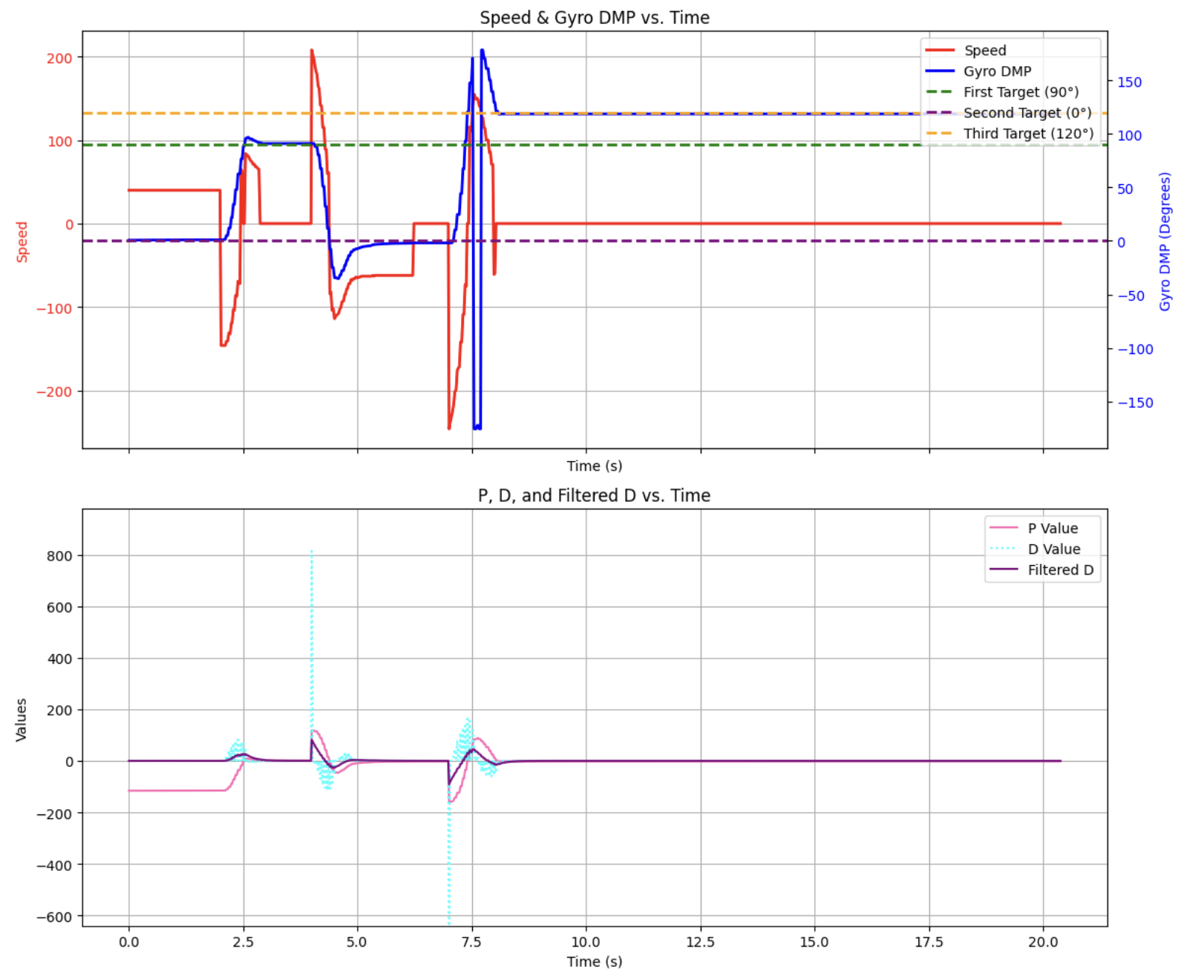
You can certianly see some more derivative kick, but again, it is filtered out well by the LPF.
Sampling Time Discussion
The IMU polling rate is set to 1.1 kHz in the line: success &= (myICM.enableDMPSensor(INV_ICM20948_SENSOR_GAME_ROTATION_VECTOR) == ICM_20948_Stat_Ok);. The sampling time for our system is the DMP output rate ODR which is set in my setup function: success &= (myICM.setDMPODRrate(DMP_ODR_Reg_Quat6, 2) == ICM_20948_Stat_Ok);. The 2 sets the ODR to an overall 549 Hz, plenty fast for the PID turning loop.
$$ ODR = \frac{\text{DMP running rate}}{\text{ODR setting}} - 1 $$
Polling rate is 1.1 kHz (1100 Hz)
$$ ODR = \frac{1100}{2} - 1 = 550 - 1 = 549 \text{ Hz} $$
Collaboration
I collaborated extensively on this project with Jack Long and Trevor Dales. I referenced Stephan Wagner’s site for much of the lab but most specifically for implementing the DMP! ChatGPT was used to help plot graphs.